Solar
Garden Light Autopsy
I had this idea to use the solar power converting
ability of
a garden light to power a PIC weather station.
So I checked out what was available at the neighborhood Home
Depot. To my surprise, they were on sale! Sixteen bucks bought me 4 lights ("How
many lights do you see, Picard?" Star Trek Next Generation) complete
with
AA size Nicads. Each light comes with 2
cells for a total of 8. What a bargain!
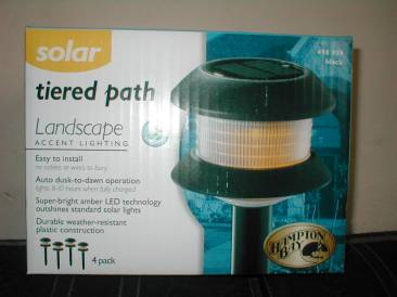
"The box" Hampton Bay #498-959 $16 at Home Depot
Next, I opened a unit.
Don't forget to remove the batteries
first. The Nicads are tightly held by
tabs on the plastic case.
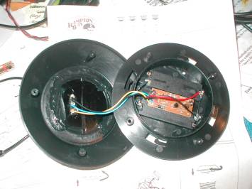
Inside the light
after removing four screws.
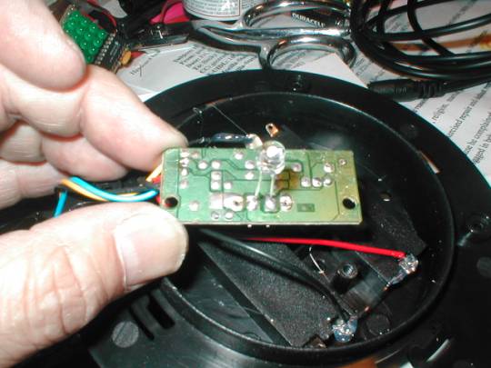
Underside of the PC
board showing yellow superbrite LED
The garden light uses a single
yellow superbright LED.
Wide Dispersal Beam.
The NiCads are charged by the solar cells through
a 1N5817
schottky diode with a low forward voltage drop. On
the top of the unit next to the solar cells is a CDS light
sensitive resistor. A PNP transistor Q1 controls power to the LED. When
the sun
is up, the CDS is conductive and turns off a second transistor (NPN
type) Q2,
effectively cutting off base drive to Q1, keeping the LED off.
When it is dark enough, the CDS is non-conductive
and allows
drive current through R3 to turn on the LED.
During the day, the LED is off and the current draw is very low.
The
solar cells can then use sunlight to charge up the batteries. Measured open circuit voltage of the solar
cell is 4.65 vdc. Current delivered to the batteries is about 75
milliamps
during charge in full sunlight. Not bad
for free energy!
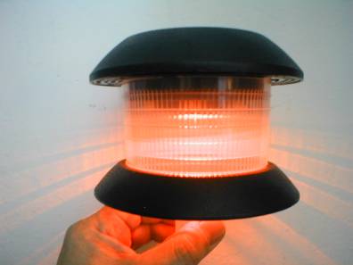
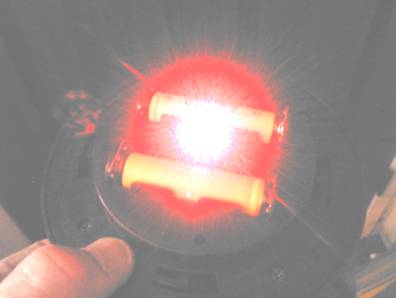
Unit running with led ON (really
bright)
So you want to tap into the limitless
resource
of solar
power?
Attach 3 wires to bring out the power from the
Nicads. One for Positive, one for
Negative, and one
for control of the LED. Controlling the led will save your battery
power when
the sun goes down. I used a Molex 3
position connector for the power tap.
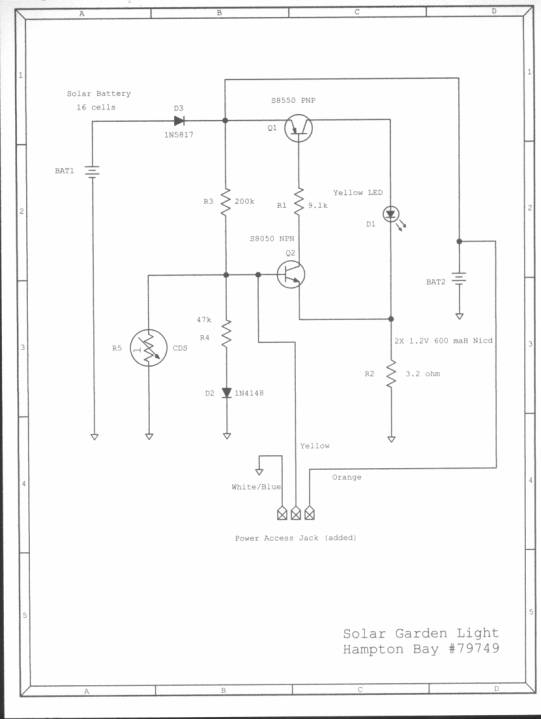
Connect to battery
positive, common and Q1 base
for led
control.
See schematic below:
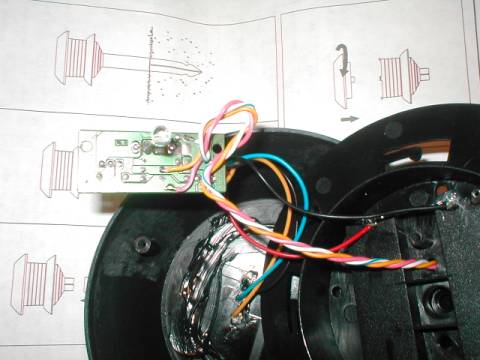
Thread
the wires out of one of the holes to the
side of the
LED in the plastic case. Attach a connector and start thinking of what
you
would like to power.
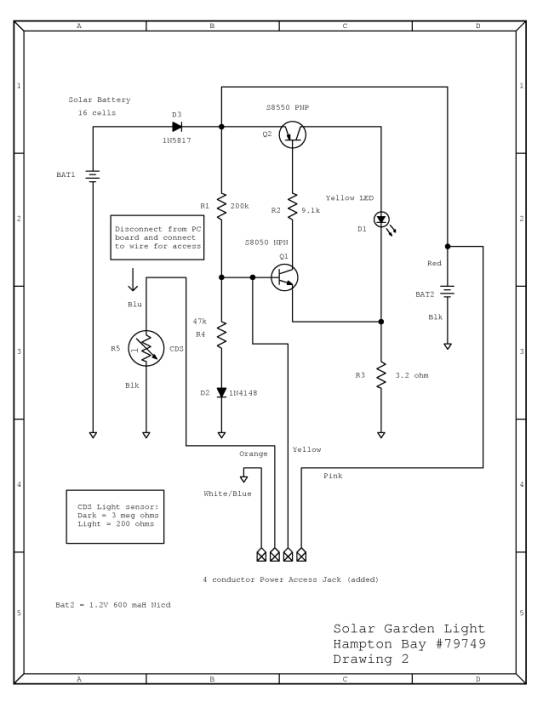
For more control
Disconnect CDS sensor wire and bring it out to
connector for
complete control of the led. Connect a series 10k resistor with the PIC. A high will turn ON the LED and a low will
turn it OFF regardless of the condition of the light sensor. I you want to keep it as the original, just
connect the cds back to the base lead by connecting the two center
leads
together at the connector.
Schematic with 4 wires connected
for more
control.
Ideas to Try
Use as a power source for PIC projects:
1. Powering a PIC
that records temperature and humidity to make a weather station.
2. Use a PIC to
blink the LED and make a beacon to freak out neighbors or use as
"runway
lights" for your driveway. Units
can be triggered by the headlights. One
unit can signal the next by using IR transmit/receive modules to make
sequential strobing without interconnecting wires.
3. Use an IR ranging
sensor such as a Sharp GP2D12 ( What we robot builders affectionately
call an
"ET" sensor) as an intruder detector. The GP2D12 requires 33
milliamps for operation. Average
current can be reduced by turning on, sense the environment, then turn
off for
a few moments. Sensors can be made
wireless
using a RF module as a link to a PC.
4. Wire several units in series for higher voltage.
5. Use a PIC to
generate random PWM to drive the base and create a "flicker effect",
making the lights seem to have a flame.
6. Use a MAX756 to step up the voltage to 5 Volts
for
projects that require regulated power.
7. Stepping up to 5
Volts will allow use of white LEDs since a higher voltage is required.
8. 5 volts could
drive RGB type of self-flashing LEDs, creating a multicolor light
effect.
PDF of this project