Test Setup
Test Setup
I started doing some experiments with developing a method to track the direction of sound.
People, animals and some insects use "Interaural Time Difference" or ITD to sense sound direction. If a pair of microphones are facing straight to a sound source, then each "peak and valley" of the sound wave will be in-phase with each other. If the sound source is to the side, each waveform would be identical, but slightly out-of-phase due to the fact that sound travels 343 meters per second and reaches the microphones at different times . By using digital processing the phase difference can be measured. A servo can be used to adjust the microphones direction until zero phase difference is attained.
Giving the ability for a robot to locate sound direction would be helpful for Search and Rescue Robots, Tactical and Reconnaissance robots for finding and locating injured people.
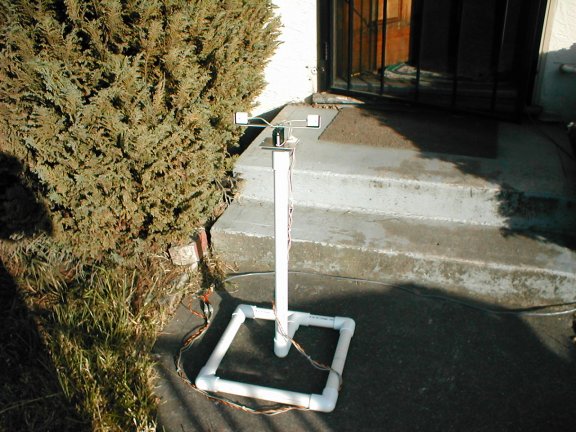
Ok now you know what this test setup is for. Just how did all this "freak out" my neighbor?
Well the lady next door thought I was tape recording conversations in the neighborhood and "invading her privacy". After all, it was a pair of microphones on a bar that can be "aimed" in different directions (the local kids just loved it!).
After being outside for only a few hours I had the police knocking on my door. They asked if they could come inside my home and view the setup and be sure I had no tape recording equipment. Eager to share what I was doing I reluctantly (after all don't they need some kind of writ or something?) showed the officers my setup and waveforms on my oscilloscope and all was well. I explained some of what I do with robots and gave them each my card with my website URL.
Experimentation will continue over the next few weeks or months. I will post my results at this website and any "close encounters of the absurd kind".
My next experiment as suggested by a dear and wise friend, is to gain the trust of my neighbors.
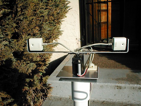
Close-up of microphones/servo with foam windscreens removed.
So if you see some funny looking robot thingy with a pair of microphones please don't Freak Out.
Robots are here to stay, get used to it!
Updated: 5-23-04
The first test to perform was to see if a change of phase can be observed as the microphones are rotated.
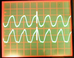
The microphones are each amplified with an opamp circuit to the gain of 100 and viewed on a dual trace scope. I used a small beeper for a sound source. Below is a photo of the setup and resulting waveform on an oscilloscope.
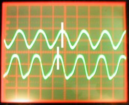
An oscilloscope trace plots voltage over time with the trace starting on the left. The "peaks and valleys" of the sound wave can be seen in real time.
Scope time base: 2 milliseconds per horizontal division.
Scope sensitivity: 200 millivolts per vertical division.
Microphone separation: 7 inches from each other and 10 inches from
the sound source.
 Top left, bottom right
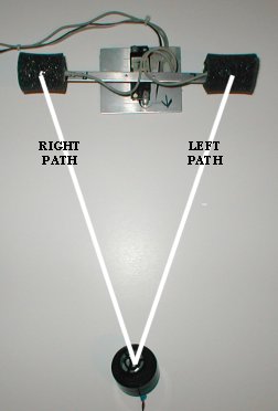
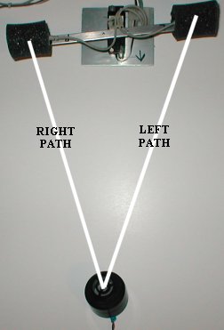
The microphones are pointing directly to the sound source.
Both
right and left sound paths are equal. The scope shows the sound
wave
to be in-phase. The top trace is the left microphone and the
bottom
trace is the right microphone.
 Top left, bottom right
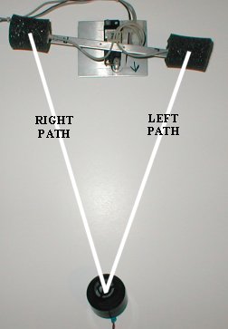
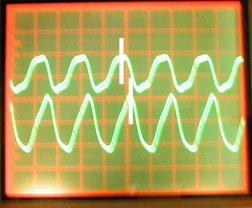
Due to the fact that the right microphone is closer to the source than the left, the "peaks and valleys" of the sound wave will arrive sooner on the right. Notice how the bottom trace (right microphone) received the sound wave a little before the left.
If the microphones are turned with the left side closer to the source, the right side will take longer. The oscilloscope trace for the right microphone shows a phase shift toward the right.
 Top left, bottom right
Next task is to digitize the waveforms to determine the difference of phase.
Important items to consider are:
A practical sampling rate will need to be determined.
Prefiltering with high-pass frequency rolloff at 1/2 of the sampling rate will be needed to prevent aliasing.
Sampling the waveforms should be done with dual ADC's along with simultaneously operating sample-and-hold amplifiers. After the samples are taken, some kind of correlating algorithm will need to be developed to determine positive or negative phase. As samples are taken the servo is adjusted until samples show good correlation between themselves.
Another idea to explore is perhaps using a third microphone in the center to act as a reference. Positive or negative phase can then be determined by comparing the "peaks and valleys" of the wave simultaneously with the reference microphone. The determined polarity can set the servo direction.
Links to view:
