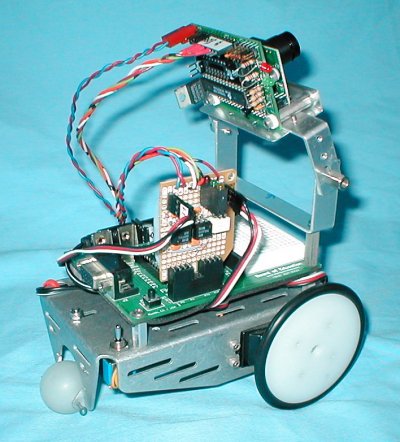
A CMUcam mounted on a Parallax Boebot
CMUcam
I always wanted to build a robot that had the ability to follow me around.
Most vision systems available are too complex or expensive for the average
robot experimenter. The CMUcam developed by Carnegie Mellon University
with built-in color tracking abilities can be purchased from Seattle
Robotics for around $100!
Mounting the camera: An aluminum mount was made to attach the CMUcam to the Parallax BoeBot. The camera's viewing angle can be adjusted by loosening the side mounted spacers. The mount is attached to the Boebot with 3/4 inch, 4-40 threaded spacers. The weight of the batteries at the base prevents the robot from falling over.
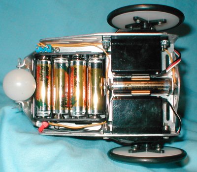
Power is controlled by a switch mounted near the back end of the Boebot.
More Power Scotty!
The CMUcam adds an additional power drain of 200 milliamps to the Boebot. Adding one extra cell to the power source allows the use of rechargeable NiMH cells. Both the Boebot and the CMUcam require at least 5.5 volts for their low drop-out regulators to operate. The use of 5 cells at 1.2 volts supplies a total of 6 volts.
The photo above shows how an extra cell in a battery holder can be fitted
between the two servos. Wire this cell in series with the other battery
holder and in series with the power switch. The Boebot chassis comes
with two holes toward the rear already drilled. A switch with a 1/4
inch threaded shaft fits in the hole. The hole is a little oversized,
but will work.
The Interface
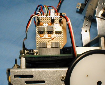
Connecting the CMUcam with opto-couplers allows the BS2 to turn the camera's power on and off, while preventing current from flowing into the camera's input when the unit is off. Isolation in this manner prevents damage to the SX28 microcontroller with the added plus of saving power when the camera is not needed.
The CMUcam's interface circuitry is fitted on a piece of Radio Shack (#276-150) perf board. Visible to the left on the board are two 740L6000 high speed opto-couplers used for serial communications. Bypass capacitors are mounted directly to the machine pin socket pins up close to the opto-couplers. The bypass capacitors require connection with short leads to the 740L6000 to remain stable.
The light colored IC on the right is a PVG312 opto-switch used to turn on and off the CMUcam. Mounted on the board are red, green and yellow status LEDs.
Connection to the servos is brought out to two 3 pin male headers mounted on the perf board.
The whole assembly plugs into the Boebot's X1 assessory connector using two 8 pin male angled headers.
RS232 Interface IC Modification
The CMUcam has on the PC board a SP232 for serial communications with a PC. When connecting the CMUcam to the BS2 on the Boebot, the IC must be removed to prevent contention between the IC and the BS2. A small "piggyback" board was made out of perf board to allow disconnecting the serial lines with jumpers.
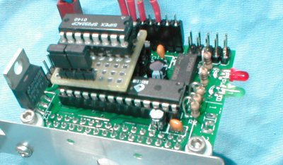
When using the CMUcam with the BS2 I just remove the two jumpers, effectively disconnecting pin 11 and 12 from the board. All other pins of the IC are straight through. The jumpers can go back when using the CMUcam with the PC. This method is easier and safer that trying to dig out the IC.
Schematic of the interface:
Tracking LED's
Under low light conditions, the camera may have difficulty tracking an object. To solve this problem, I tried having the CMUcam track a red LED. At first the LED was so bright to the camera that it appeared as a bright white blob. Dimming the LED's brightness and using a plastic diffuser helped enough for the Boebot to track a LED mounted on a stick. If I put the LED in front of the robot, it will follow it around.
Using a Java GUI that can be downloaded from the Seattle Robotics Web site, here's a screen dump of the LED.
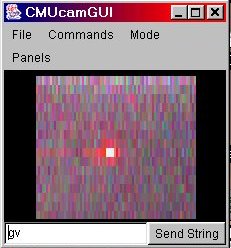
Notice white center caused by LED being too bright.
The color parameters for the center spot are Red 240, Green 240, Blue
240
Total adds up to white.
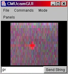
Dimmed LED shows correct color to camera.
The color parameters are Red 240, Green 18, Blue 18 for the red LED
I was using.
The image has lower resolution when running at 9600 baud. The cam has
the ability to produce a 80 x 143 resolution at 115,000 baud.
![]() Download
.bs2 Program, a modified example from Parallax, Inc.
Download
.bs2 Program, a modified example from Parallax, Inc.
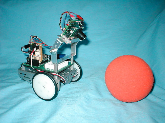
Cambot looks intently upon an orange poof-ball.
![]()