The Fingerboard II© from EAS can run IC4 if one of the "missing " Handy Board© circuits is added.
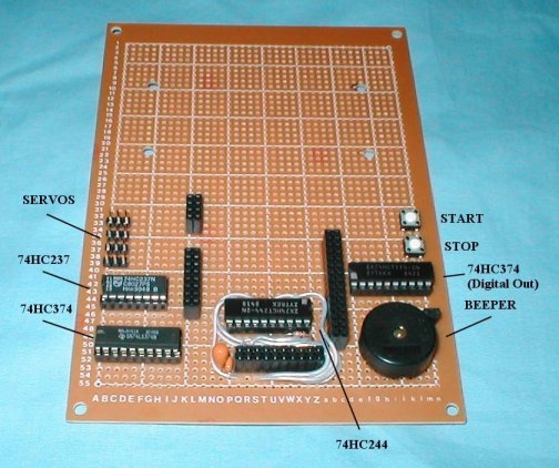
Adding a 74HC244 to JP9 allows IC4 to read the "start" button, otherwise IC4 thinks the start button is pushed down at powerup and is instructed not to run main.
The circuit adds the start and stop button functions and 6 digital inputs, equal to pins 4 to 9 of J2 on the Handy B oard.
You can add a piezo beeper to JP12. Fingerboard will run with or without LCD (DMC16249).
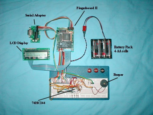
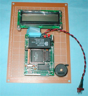
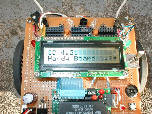
Photo of test setup running IC4, version 4.21
Schematic of Circuit:
void main() {
while(1) {
set_beeper_pitch(500.0);
beeper_on();
msleep(100L);
beeper_off();
msleep(100L);
}
}
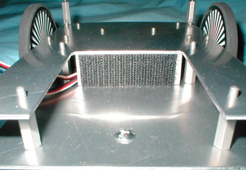
The next series of photos will show the construction progress of a Fingerboard robot. The robot is experimental and not complete. Check this site for updates.
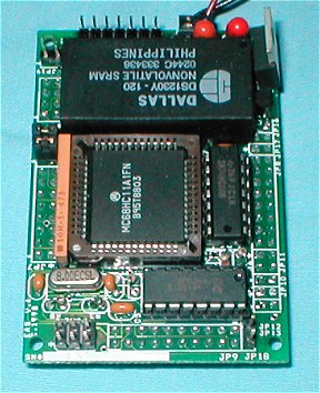
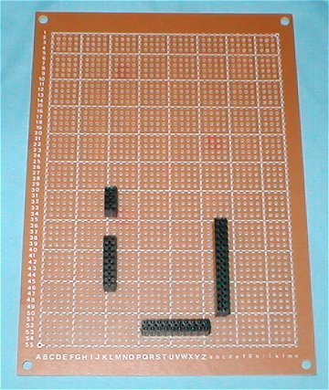
First, get a blank board from EAS and build the Fingerboard II.
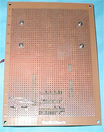
This is the main MCU board that runs the 68HC11. Toward the top is a Dallas DS1230Y non-volatile memory that can keep the program for up to 10 yrs without external power. A built-in dual lithium battery circuit maintains the memory. You can operate as low as 6 volts if you use a low drop-out regulator such as a LM2931T-5.0.
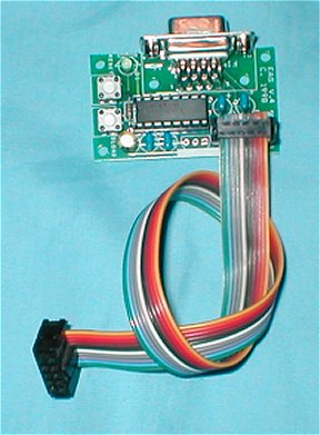
The fingerboard II comes with a serial adapter board for connection to your PC's serial port. The serial adapter board has both Download and Reset buttons. Use a serial extension cable to connect to the board, then connect ribbon cable to the fingerboard. The ribbon cable only needs 6 terminals. Finding such a connector difficult, I used a standard 10 pin IDC connector and plugged up the unused socket holes with header pins.
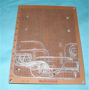
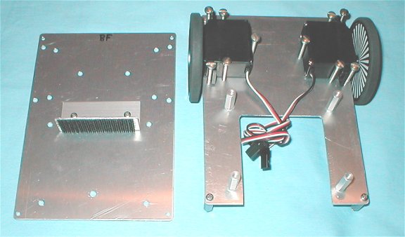
Use a Radio Shack© 276-147 general-purpose IC PC Board for adding circuits to your Fingerboard II. Use female dual row headers to bring connections from the fingerboard to the robot. For really clean soldering, use Kester #24-6337-6403, "331" flux Organic Core Solder. The flux will wash off with hot water and leave a clean surface. Dry off after washing with a hair dryer. You can get this solder in 1 lb rolls at Digikey.com or sometimes at Fry's Electronics, if you have one in your area. Do not leave the flux residue on for more than 12 hours or you risk damage to the board.
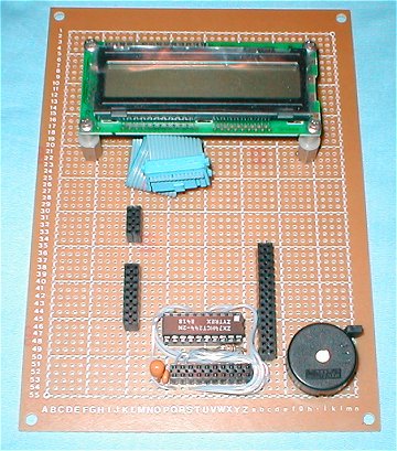
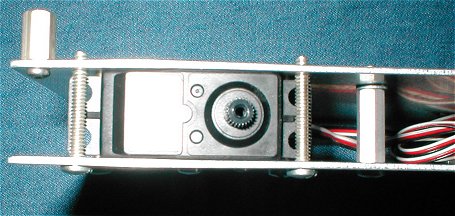
Next add some of the "missing Handy Board circuits" to allow the fingerboard access to sensors and servos. I use the "teflon tubing and tinned wire" method for wiring. You could use wire-wrap.
Robot Schematic: Warning: More circuitry to be added. This project
is
a "work in progress".
Schematic as PDF (new 8-23-03)
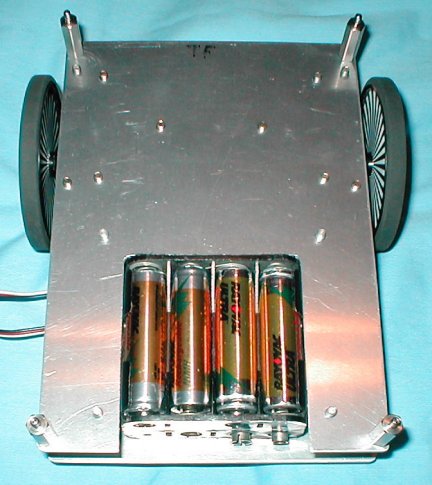
A piece of velcro on some 3/4 x 3/4 angle is used to hold the battery holder. Place a second piece of velcro on the battery holder itself.
Battery Power:
A 6 volt battery pack did not supply enough to power to the
fingerboard.
When the servos turned on, a voltage drop caused a reset. I use 8
"AA" NiMH cells for the power source. Power to the servos is
series
regulated with a 7805 regulator. A diode is inserted in the
common
leg of the regulator to bring up the voltage to 5.6 volt. A second 5
volt
regulator is on the fingerboard and is used for the 5 volt source.
Using
a battery holder allows changing a bad cell. No need to waste an
assembled battery pack just because a cell went bad. A charging
circuit
will be designed and added to the robot.
Tamiya 70144 Ballcaster mounted on the bottom of the robot.
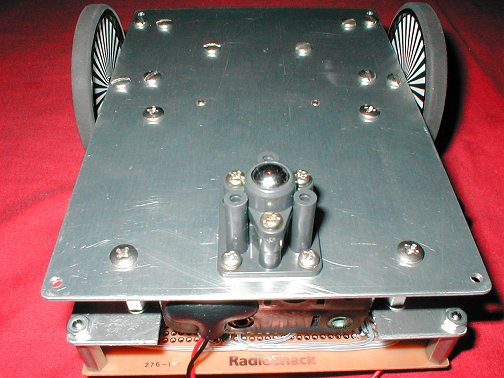
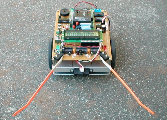
Photo shows robot is running IC4 ver. 4.21G. Handy Board compatible connectors are at the front. Expansion plug-ins can be added.
On-board sensors are; 2 bump whiskers, 2 phototransistors for light direction, 38kc IR detector, battery voltage (to be added), "starboard and port" led indicators.
Forward obstacle detection using a Sharp GP2D12 analog sensor placed at the front.
Possible future plug-in modules; sonar, line following, sound direction, CMUcam©, H-bridge motor drive.
Front view with Sharp GP2D12 at the front.
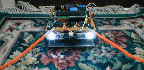
A pair of white leds are added to the front of the robot. I
used
Kingbright L7114PWC/H from the X-Bright series. The led can put out
4000
mcd's at 20 ma. I plan to use the leds when I add the CMUcam.
Test Programs written in Interactive C (Ver.4.21g)
Avoid1.IC Program that uses whiskers and a GP2D12 to avoid objects.
Liteseeker.IC Program instructs the robot to move toward light using the on-board phototransistors.
SeekAvoid.IC Combination of seeking light and avoiding objects. Flashes white leds in front
Tablerover1.IC Mount
the ET sensor tilted 45 deg to view tabletop. Robot will not run off a
tabletop as it travels.
Added ability to balance wheel speed with the user knob.


Let me know if you would like to see this project available as a PC board or kit.
![]() To "Robot Related Projects"
To "Robot Related Projects"