PIC's are low-cost, easy to use microcontrollers from Microchip. The 12F, 16F and 18F series, both having flash memory and the ability to be programmed "in-circuit", allows designs to be tested during the creation of the program.
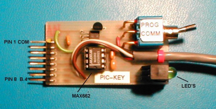
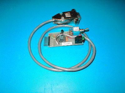
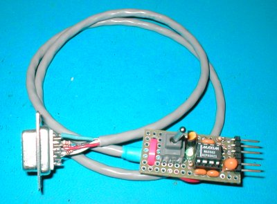
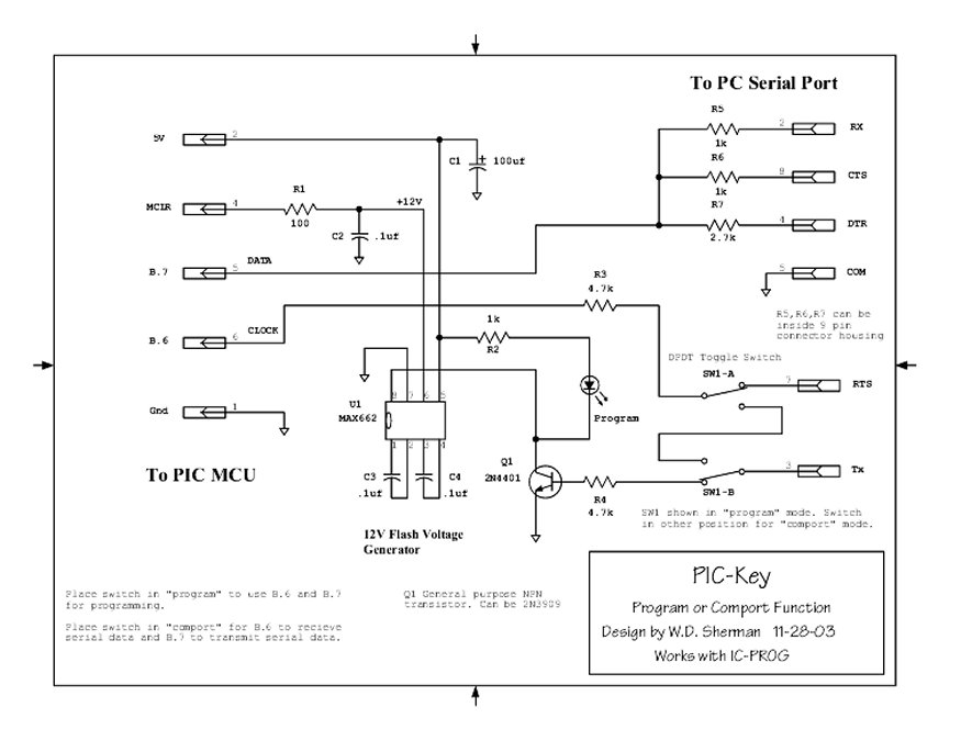
The PIC-KEY was constructed on a home-made PC board, along with a short cable to connect to the PC's serial port. To help keep the device small, I used surface mount resistors along with the other components. A piece of pref-board can be used instead. The 12 volts for programming is generated by a MAX662 from the 5 volts supplied by the protoboard. The IC is may be difficult to get these days, try Mouser Electronics and use a ST662ACN, a subsitute.
This tool works with IC-PROG software (it's free) as a PIC programmer. Set IC-PROG to program as type "JDM" . I have successfully programmed 16F877, 16F876, 16F628, 16F84, 18F452, 12F675 and 12F629.
Disclaimer:
You are free to use any of the circuits on my
webpages
for personal or educational use and not for commercial use.
These designs are experimental and may not fully
work
for you. I will not be responsible for any damages to any
computer,
equipment, mental or bodily injury, or for lost revenue due to the use
of these designs.
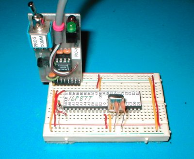
To make the whole process of PIC circuit design flexible and allow creativity, I like to start with a circuit on a socket strip proto-board. Programming is done by plugging the PIC-KEY into the socket strip along with a PIC, a 16F877 in this example. Components can be added and changed as needed without soldering. The PIC-KEY can be left on the board during the whole design process. Once your design is complete, a more permanent version can be made on prefboard or PC board material.
Another handy tip is to make a sticky label (see photo below) to show the port names on the PIC. I made up a sheet of labels using Corel Draw and stuck them on with a glue stick; sure saves time and frustration when identifying those pins.
PIC Lables .CDR Corel Draw format
The alignment of the pins of the PIC-KEY along with the PIC allow programming and serial in/out communications with the PC serial port.
The PIC-KEY is powered off the proto-board, not the serial port. Because both the Pic and the computer share the common, the PIC-KEY may remain powered while connected. Most cheap programmers that draw power from the serial port cannot remain connected when running the Pic normally.
Connections are as follows from left to right:
Common, +5, Blank pin, Programming V (MCLR), B7, B6, B5, B4
A diode in series with a 10k resistor connects +5 to MCLR to provide reset. Power to the PIC-KEY comes from the top or bottom rails of the proto-board. B7, B6, B5, B4 run directly to the PIC. B7 and B6 are used by the PIC for programming, while B5 and B4 are used for serial communications. Light emitting diodes indicate programming and communication activity. A switch was added to change connection to the serial port as needed for programming or communications.
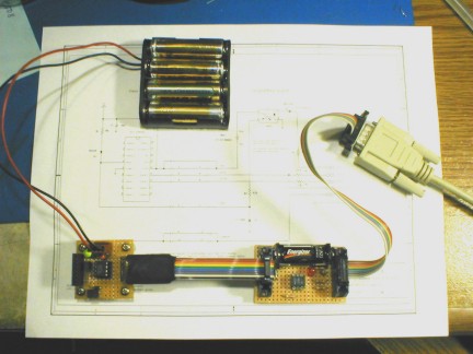
Photo below shows the position of the PIC-KEY plugged into the proto-board. Top and bottom rails should connect to your power source for the PIC. I used four series-connected "AA" NiMH type batteries in a plastic battery holder. Don't use alkaline batteries, these will supply 6 volts, too much voltage for the MAX662A IC used in the programmer.
Important Note: Be sure to add a bypass cap at the PIC's Vdd and Vss supply leads. Use 4.7 to 100uf capacitor. You can add the capacitor to the PIC-KEY.
Click
on this link for a tutorial on the use of bypass capacitors.
New designs of the PIC-KEY
The idea of sharing B.6 and B.7 for both programming and serial port use was first suggested by Vladimar Skrypnik. Thank you for your idea and correspondence.
Additional loading caused by adding the RX line on pin 2 of the
serial
port may lower the voltage at B.7. If the voltage is lower than 5
volts, you may need to lower the value of R7.
It has been discovered if you use B.7 (data) or B.6 (clock) as an output and is made HIGH very early in your program (like the first line), problems with reprogramming may occur. IC-Prog cannot assert B.7 or B.6 with the Pic-key if it is High after MCLR is raised to 12 volts. If you pull out the xtal before programming, cycle the power or do a reset, the problem seems to go away. Just remember to replace the xtal after programming. Or if you interrupt power quicky, just as the programming light comes on, programming will progess. The best solution for now is simply reserve B.7 and B.6 for programming or use as inputs and use the other lines for I/O. My Optopicker does not have this problem because of using switched +5 to the PIC. Presently I am working on ways to get around this bug. When designing boards that use ICSP it is always desirable to use jumpers to isolate the B.6, B.7 lines. Doing so will prevent excess loading during programming and prevent those circuits from operating during a programming session.A Programming Note:
If anyone makes some
discoveries, has problems
or ever built a Pic-key, please send email and let me know. (see bottom
of page)
Test Circuit
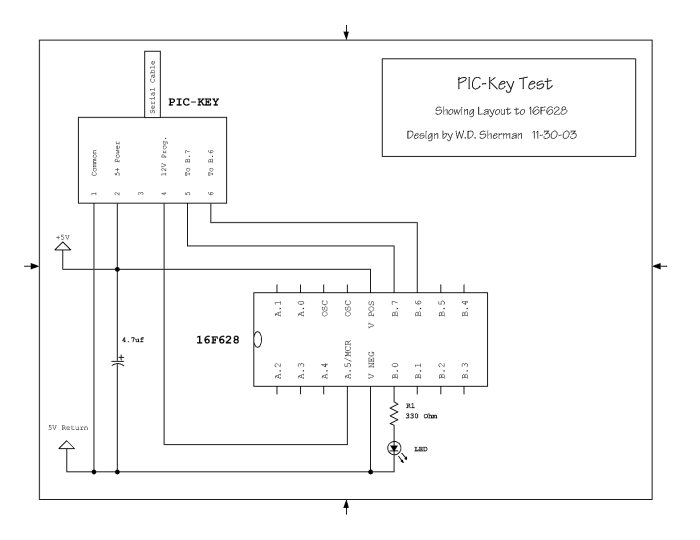
pickeytest.pdf
Can't get a
MAX662?
Here's a design that
uses a opto-coupler instead of the MAX662 Updated 10-28-04
Optopicproger2.pdf uses a CD4050 CMOS buffer for low power serial ports.
Test your PIC-key with IC-PROG's "Check Hardware" function. I made up a special page for setting up IC-PROG.
16F628
Load a 16f628 with the hex file serialinout.hex.
With the Pic-key connected to your PC serial port, start a terminal
(2400-N-8-1)
program such as Hyperterminal. Your monitor will
show the keystroke after B.0 blinks an LED.
16F876
If you want to use a 16f876 use this file.
ser876.hex
Pic Pro Basic file ser876.bas
Pic Pro basic assembly file ser876.asm
Use a 4 mhz Xtal and set com to 2400-N-8-1
' Test Program
' Use intRC I/O in the config.file and turn off
all fuses.
' Test program to blink an LED connected to PORTB.0 (pin 6) and
' send/receive serial data using B.6 and B.7
' Fuses IntRC I/O, no WDT'
' Written in Pic Pro Basic for 16f628 to test pickey prog/comport.'
' Bill Sherman 11-18-03'
Include
"modedefs.bas"
' Include serial modes'
n var byte
loop:
'get a keyboard letter and display value after flashing led'
serin portb.6,N2400,n
High
portb.0
' Turn on LED connected to PORTB.0
Pause
50
' Delay for 50 milliseconds'
Low
portb.0
' Turn off LED connected to PORTB.0
Pause
50
' Delay for 50 milliseconds'
Serout portb.7,N2400,[n]
Goto
loop
' Go back to loop forever'
End


Let me know if you would like to see this project available
as
a PC board or kit.
![]() Back to Electronic Projects
Back to Electronic Projects